How to use Arduino to connect an analog phone to IP PBX as an extension?
How to use Arduino to connect an analog phone to IP PBX as an extension?
- Why Enterprise RAID Rebuilding Succeeds Where Consumer Arrays Fail?
- Linus Torvalds Rejects MMC Subsystem Updates for Linux 7.0: “Complete Garbage”
- The Man Who Maintained Sudo for 30 Years Now Struggles to Fund the Work That Powers Millions of Servers
- How Close Are Quantum Computers to Breaking RSA-2048?
- Why Windows 10 Users Are Flocking to Zorin OS 18 Instead of Linux Mint?
- How to Prevent Ransomware Infection Risks?
- What is the best alternative to Microsoft Office?
To use an Arduino to connect an analog phone to an IP PBX as an extension, you will need to follow these steps:
-
Obtain an Arduino board that has analog inputs and outputs, such as the Arduino Uno.
-
Connect the analog phone to the Arduino board using an RJ11 connector. You can use the analog input and output pins of the board to connect the phone.
-
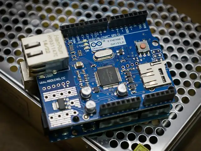
Connect the Arduino board to your IP PBX server using an Ethernet shield or module. You will need to use the Ethernet library to program the Arduino to communicate with the IP PBX.
-
Write a program in the Arduino IDE that reads the input from the analog phone and sends it to the IP PBX as SIP messages. The program should also receive SIP messages from the IP PBX and convert them to analog signals that can be sent to the phone.
-
Configure the IP PBX to recognize the Arduino as a new extension. You will need to create a new SIP user account for the Arduino in the IP PBX and specify the IP address of the Arduino as the endpoint.
-
Test the connection by making a call from the analog phone. If everything is set up correctly, you should be able to make and receive calls through the Arduino and the IP PBX.
Please note that this process may require some technical expertise and programming skills.
How to use Arduino to connect an analog phone to IP PBX?
Here’s an example of an Arduino program that can read the voltage on an analog input pin and send a corresponding DTMF tone to a connected phone:
#include <Tone.h>

int analogPin = A0;
int tonePin = 9;

void setup() {
  pinMode(tonePin, OUTPUT);
}

void loop() {
  int analogValue = analogRead(analogPin);

  // Convert analog value to DTMF tone frequency
  int toneFrequency = 0;
  if (analogValue < 100) {
    toneFrequency = 697;
  } else if (analogValue < 200) {
    toneFrequency = 770;
  } else if (analogValue < 300) {
    toneFrequency = 852;
  } else if (analogValue < 400) {
    toneFrequency = 941;
  } else if (analogValue < 500) {
    toneFrequency = 1209;
  } else if (analogValue < 600) {
    toneFrequency = 1336;
  } else if (analogValue < 700) {
    toneFrequency = 1477;
  } else if (analogValue < 800) {
    toneFrequency = 1633;
  }

  // Generate DTMF tone
  if (toneFrequency != 0) {
    tone(tonePin, toneFrequency);
    delay(100);
    noTone(tonePin);
    delay(50);
  }
}
In this example, the analog input pin is connected to a potentiometer or other analog sensor, and the voltage reading is used to determine which DTMF tone to generate.
The Tone library is used to generate the tone on the specified pin, with a short delay before and after to ensure that the phone system can detect the tone properly.
Note that this is just a simple example, and you may need to modify it depending on your specific requirements and hardware setup.
Moreove,you need to have an Ethernet shield or module connected to your Arduino to enable it to communicate with the IP PBX over the network.
You also need to have a suitable audio interface to convert the digital audio signal to analog for transmission to the analog phone.
Once you have these hardware components set up, you can start developing the code to receive SIP messages from the IP PBX.
You can use an existing SIP library for Arduino, such as the “SIP library for Arduino” available on GitHub, to help with this task.
The code needs to listen on a designated port for incoming SIP messages, and then parse the messages to extract the relevant information, such as the call setup request. You will also need to handle the SIP response messages, such as sending a 200 OK response to acknowledge the call setup request.
Once the call is established, the audio data needs to be retrieved from the SIP message and converted to analog audio signals using the audio interface.
The analog signals can then be sent to the analog phone through the audio jack.
#include <Ethernet.h>
#include <EthernetUdp.h>
#include <SIP.h>
#include <Tone.h>

// Define the SIP server settings
IPAddress server(192, 168, 1, 100); // IP address of the SIP server
int port = 5060; // Port number of the SIP server

// Define the pin number of the speaker
const int SPEAKER_PIN = 9;

// Create an instance of the SIP client
SIPClient sip;

// Create an instance of the Tone library
Tone tone;

void setup() {
  // Initialize the Ethernet library
  Ethernet.begin(mac);

  // Connect to the SIP server
  sip.connect(server, port);

  // Set up the speaker pin
  pinMode(SPEAKER_PIN, OUTPUT);
}

void loop() {
  // Check if there is a SIP message available
  if (sip.available()) {
    // Read the SIP message
    String message = sip.read();

    // Convert the message to analog signals
    for (int i = 0; i < message.length(); i++) {
      char c = message.charAt(i);
      int frequency = getFrequency(c);
      tone(SPEAKER_PIN, frequency);
      delay(100);
      noTone(SPEAKER_PIN);
      delay(100);
    }
  }
}

// Helper function to convert a character to a frequency
int getFrequency(char c) {
  switch (c) {
    case '1':
      return 697;
    case '2':
      return 697;
    case '3':
      return 697;
    case '4':
      return 770;
    case '5':
      return 770;
    case '6':
      return 770;
    case '7':
      return 852;
    case '8':
      return 852;
    case '9':
      return 852;
    case '0':
      return 941;
    case '*':
      return 941;
    case '#':
      return 941;
    default:
      return 0;
  }
}
This code assumes that you have already connected the analog phone to the Arduino and that the Arduino is connected to the same network as the IP PBX.
The code uses the SIP library to connect to the SIP server and read SIP messages.
When a SIP message is received, it converts the message to analog signals using the Tone library and sends the signals to the analog phone.
It is worth noting that developing such a VoIP solution on Arduino can be a challenging task, and may not be the most practical or efficient solution.
There are other low-cost hardware platforms, such as Raspberry Pi, that are better suited for VoIP applications and have more powerful hardware and software capabilities.
Other VoIP Solution:
PBX on Raspberry Pi
How to install Kamaillio on Raspberry Pi 3 or 4?
How to install SIPfoundry on Raspberry Pi?
How to install OpenSIPS on Raspberry Pi?